
Part I: Antenna Models and Construction
This two-article series is devoted to a dipole family of antennas used in EMC testing: half-wave dipole, quarter-wave monopole, log-periodic, and biconical antenna. Part I presents the antenna models and the construction details. Part II focuses on the antenna impedance, VSWR, and the radiated emissions measurements.
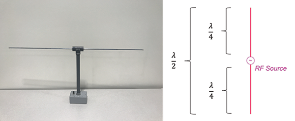
Half-Wave Dipole Antenna
Half-wave dipole antenna, shown in Figure 1, consists of a thin wire fed or excited at the midpoint by a voltage source. The total length of a dipole equals half-wave length. Each leg of a dipole has a length equal to the quarter of a wavelength.
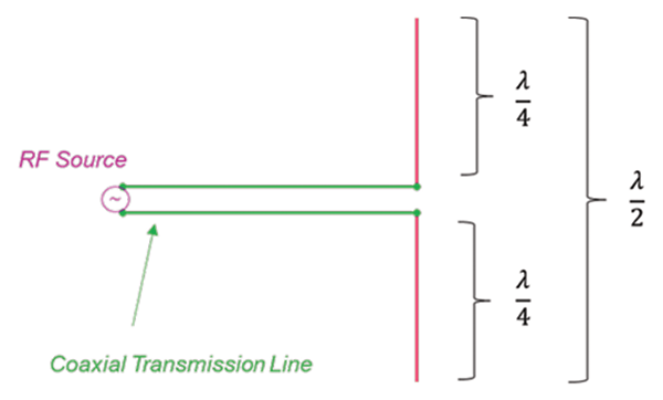
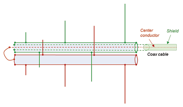
In many practical applications the half-wave dipole antenna is connected to an RF source via a coaxial cable, as shown in Figure 2.
Ideally, the current from the source flows as a conduction current, ![]() C, along the transmission line, through the upper arm of the antenna structure, then it flows as a displacement current,
C, along the transmission line, through the upper arm of the antenna structure, then it flows as a displacement current, ![]() D, through a parasitic capacitance between the antenna arms, then it returns to the source as a conduction current through the lower arm and the coaxial cable [1]. This is shown in Figure 3.
D, through a parasitic capacitance between the antenna arms, then it returns to the source as a conduction current through the lower arm and the coaxial cable [1]. This is shown in Figure 3.
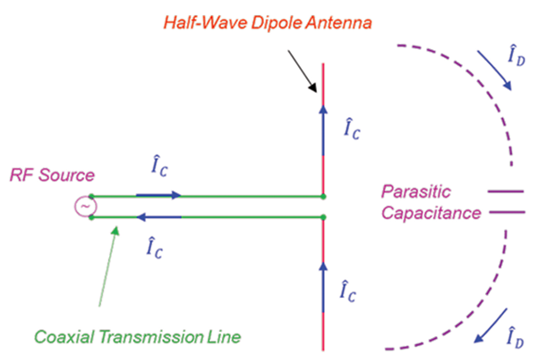
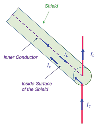
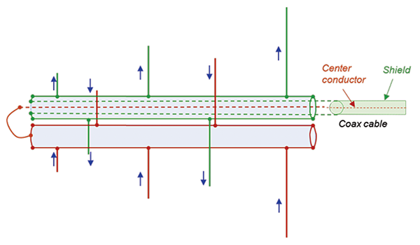
Figure 4 shows the details of the current flow in the center conductor and (ideally) the shield of the coaxial cable.
With respect to the geometry shown in Figure 5, the half-wave dipole far electric field, ![]() θ, and far magnetic field,
θ, and far magnetic field, ![]() φ, are given by [2],
φ, are given by [2],
![]() (1)
(1)
![]() (2)
(2)
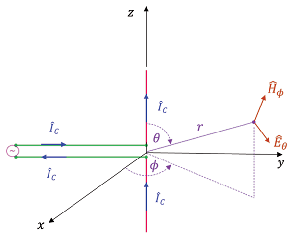
where I is the amplitude of the conduction current, η0 is the intrinsic impedance of free space, and β0 is the phase constant related to the wavelength λ0 in free space by
![]() (3)
(3)
F(θ) is the space pattern given by
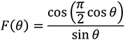 (4)
(4)
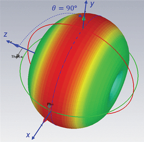
The fields are at their maximum broadside to the antenna, i.e., for θ = 90°, when F(θ) = 1. Figure 6 shows the radiation pattern of a half-wave dipole.
Quarter-Wave Monopole Antenna
Quarter-wave monopole can be obtained from a half-wave dipole by replacing one of the arms of the dipole by an infinite ground plane. Infinite ground plane is, of course, not realistic; a practical quarter-wave antenna has a finite-dimension ground plane, like the one shown in Figure 7.
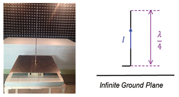
The radiation pattern of a quarter-wave monopole above the ground plane is the same as that for the half-wave dipole.
Log-Periodic Antenna
Half-wave dipole, and quarter-wave monopole antennas radiate equally in any plane perpendicular to the antenna axis, i.e., they radiate equally in any φ direction. In the EMC radiated emissions and immunity measurements it is often desired to focus the radiated signal in a particular direction. This can be accomplished by forming an antenna that consists of an assembly (an array) of the radiating elements [3]. Log-periodic antenna, discussed in this section consists of an array of the half-wave dipole antennas.
Log-periodic antenna is one of the most common antennas used in EMC measurements. It is a broadband antenna and it is usually used for the measurement of the radiated emissions from 200 MHz to 1 GHz. The log-periodic antenna consists of a sequence of parallel linear dipoles forming a coplanar dipole array, as shown in Figure 8.
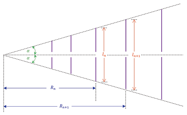
The dipole lengths increase along the antenna while keeping the angle α constant. The lengths l and the spacing R of adjacent elements increase logarithmically as defined by the inverse ratio
 (5)
(5)
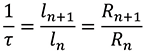
All the dipole elements of the log-periodic antennas are connected and fed at the small end of the structure. Figure 9 shows such a connection for a PCB log-periodic antenna.
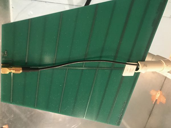
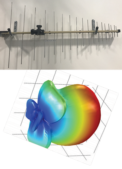
Figure 10 shows a log-periodic antenna used for EMC radiated emissions measurements in the frequency range 300 MHz – 1 GHz.
The details of the coaxial line connections for this antenna are shown in Figure 11.
coaxial cable
The dipole connections shown in Figure 11 create the current flow in the radiating elements as shown in Figure 12.
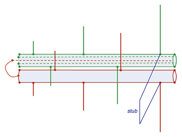
Note that the currents in the adjacent elements are 180° out of phase. At any given frequency only a fraction of the antenna is used (where the dipoles λ/2 are long). Since the phase between the adjacent closely-spaced elements shorter than λ/2 is opposite, the fields radiated by them tend to cancel out. The elements longer than λ/2 present a large impedance and carry only a small current. Often, a stub is placed at the back of the antenna (to suppress reflections) as shown in Figure 13.
The phase reversal between the short elements produces a phase progression so that the energy is beamed in the direction of the shorter elements. Radiation pattern of the log-periodic antenna is shown in Figure 14.
Biconical Antenna
Biconical antenna, shown in Figure 15, is another type of a dipole antenna commonly used for the measurement of the radiated emissions from 30 MHz to 200 or 300 MHz.
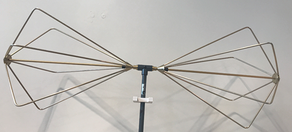
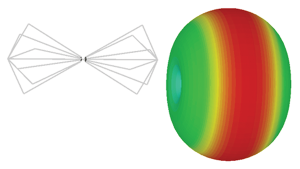
Biconical (bicon) antenna belongs to the dipole family of antennas and is classified as an intermediate bandwidth antenna. Radiation pattern of the bicon antenna is shown in Figure 16.
Normally, an EMC bicon antenna has a balun [1], shown in Figure 17, attached at the input to the antenna to make it a balanced structure.

References
- Bogdan Adamczyk, “Balanced-Unbalanced Antenna Structures and Baluns,” In Compliance Magazine, October 2019.
- Bogdan Adamczyk, Foundations of Electromagnetic Compatibility with Practical Applications, Wiley, 2017.
- Constantine A. Balanis, Antenna Theory, Wiley, 2005.