J-Pole Antennas for GPS
June 28, 2017 Leave a comment
I normally use commercial antennas for GPS (e.g., patch antennas with a magnetic mount), but I needed more antennas than I had so I built a couple of J-Pole antennas for 1575 MHz.
I started with dimensions from an on-line calculator and built an antenna using a 1mm enameled copper wire. The return loss (SWR), measured with a portable VNA, was not good. I started again with a slightly longer antenna, which resonated about 100 MHz too low, and started cutting it until it resonated on 1575. The return loss is about -15dB; not great, but good enough. Given that there are 3 different dimensions to worry about (the length of the radiating half-wave section, the length of the quarter-wave matching section, and the location of the tap on the matching section), I decided not to try to tweak it to perfection.
Here is the result:
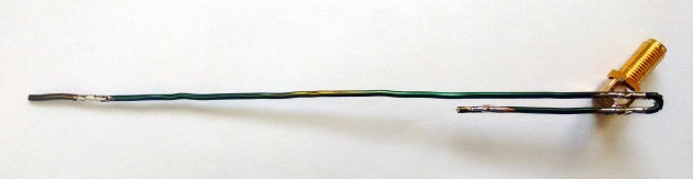
The antenna is soldered directly to two terminals of an SMA connector. This is a through-hole PCB connector, which has 5 terminals (5 for ground and 1 for the center conductor). I chopped 3 of the ground terminals so only two were left protruding, and I soldered them to the antenna.
I then made a second antenna with the same dimensions; it produced a -15dB return loss on the first try.
The length of the λ/4 stub in my antennas is 45mm, the lenght of the λ/2 radiator is 102.5mm, separation between the arms of the sub is about 3mm, and the feed point about 8mm from the shorted end of the stub.
In one of the antennas I inserted a 1000pF 0603 ceramic capacitor between the center conductor of the connector and the antenna, so that it does not short at DC. This allowed it to be used with GPS receivers that provide bias voltage to an LNA. Without the capacitor, the antenna shorts the GPS receiver, since the bias voltage is usually not current limited.
With this antenna connected to a NavSpark Mini GPS receiver outdoors, I was able to easily get a fix.

