My newest radio, the HF Signals sBitx v2, is an HF radio with so many features that you just need to follow this link over to their website to see what it is capable of. Once you have finished going down that rabbit hole, come back over here to see what mods I have done to mine already for my POTA stuff. I want to say this right away, this radio is kind of in Beta, so if you don’t like to open up the radio and tinker with it in both the software as well as the hardware, this probably isn’t the radio for you. With that out of the way, let’s get started!

I decided to get in on this idea of a open source architecture radio design. I found this company, HFSignals, and they make several radios with their latest model being the sBitx V2. This is a touch screen radio with a huge screen and it is powered by a Raspberry Pi SBC. Using a legit computer to power the radio unlocks so many things that this radio can do that other radios can not do. For one, it will do FT8 IN THE RADIO! Yeah, no external computer needed at all, that in itself is a gamechanger and don’t be surprised if you see the big names in the industry doing this in the near future because of it. By using a Raspberry Pi SBC for the brains, this little machine is just chocked full of goodies that those other radios cant do.

FT8 is native inside the radio on the sBitx v2.
You heard that right, as I type this blog post it is on the bench next to me finishing a QSO with I1RJP, and when it does it will automatically put the QSO in my log for me. How awesome is that? Did I mention it is open source? Yeah, both the software AND the hardware are open source and it is encouraged to take your radio apart and tinker with it. Shoot, it even shipped to me with a spare set of output transistors in the accessory bag. These are well thought out but they are still rather simple overall designs with features like they are passively cooled radios and use a crystal filter network. Another thing about being passively cooled is that it means there is no fan noise to deal with at all this way, since there are no fans.
Well… I used it on a POTA activation and the little radio got HOT. Really hot to be honest. So I decided that since this radio is designed from the outset to be open source and to be tinkered with by the end user and I wanted to use it for POTA activations, that I would add some fans to cool the little machine on activations.
The first thing I wanted to tackle was the power amplifier heat sink. It is a great heat sink and does a wonderful job as it became really hot during the activation. I first started looking for a suitable fan in my junk box and found the perfect fan in an old computer power supply that I have cut apart for another project. The fan was still mounted in the sheet metal case which also happened to fit perfectly over the outer edges of the heatsink. All I needed to do was trim the sides down so it sat next to the heatsink and add some screw holes to attach it with.

Once I had it mounted with a couple of self threading screws, it was time to get it running. I went inside the radio and started looking for a suitable place to tap power out to it and found the incoming source point was the best, but the fan would run all the time if I used this spot…

Enter a simple electronic circuit that could be used for any temperature of fan control and could even be adjustable with a potentiometer if you were so inclined. This circuit is a simple power transistor rated for 6 amps of max draw (I used this so it could handle the 300mA of draw from the fan and not need a heat sink and they are still really cheap too). You simple have a voltage divider network for the base of the transistor where you have a fixed resistance between the base and ground and you add a thermistor (a temperature reactive resistor) between the voltage source and the base.

I chose a 10K ohm negative coefficient thermistor for my needs as this design has the resistance go down as the temperature goes up. The fan is simply wired in series with the transistor’s collector and the voltage source and the transistor is basically used as a electronic relay in the simplest form. I know the MOSFETS are more efficient, but this works and I had all of these parts (except the thermistor) on hand so I used these instead.

What happens during operation is that when powered up, the thermistor has so much resistance at a lower temperature that the base voltage is less than the .7 VDC required to bias the transistor since the fixed resistance of the base to emitter side of the voltage divider is calculated for the desired temperature. The thermistors have a chart showing the resistance at different temperatures so you can make these calculations fairly easily. Mine worked out to 270 ohms for the fixed resistance between the base and emitter. So you can imagine that with 10,000 ohms (at 77 degrees) on the other half of the voltage divider you only get .363 VDC on the base of the transistor and the transistor stays “OFF”…

I found the above chart online for 10k ohm thermistors and grabbed it for reference only. This may not be the right chart for your thermistor as they have different resistance curves so check with your brand of device and make sure you have the right chart for your device. Back to the story in progress…
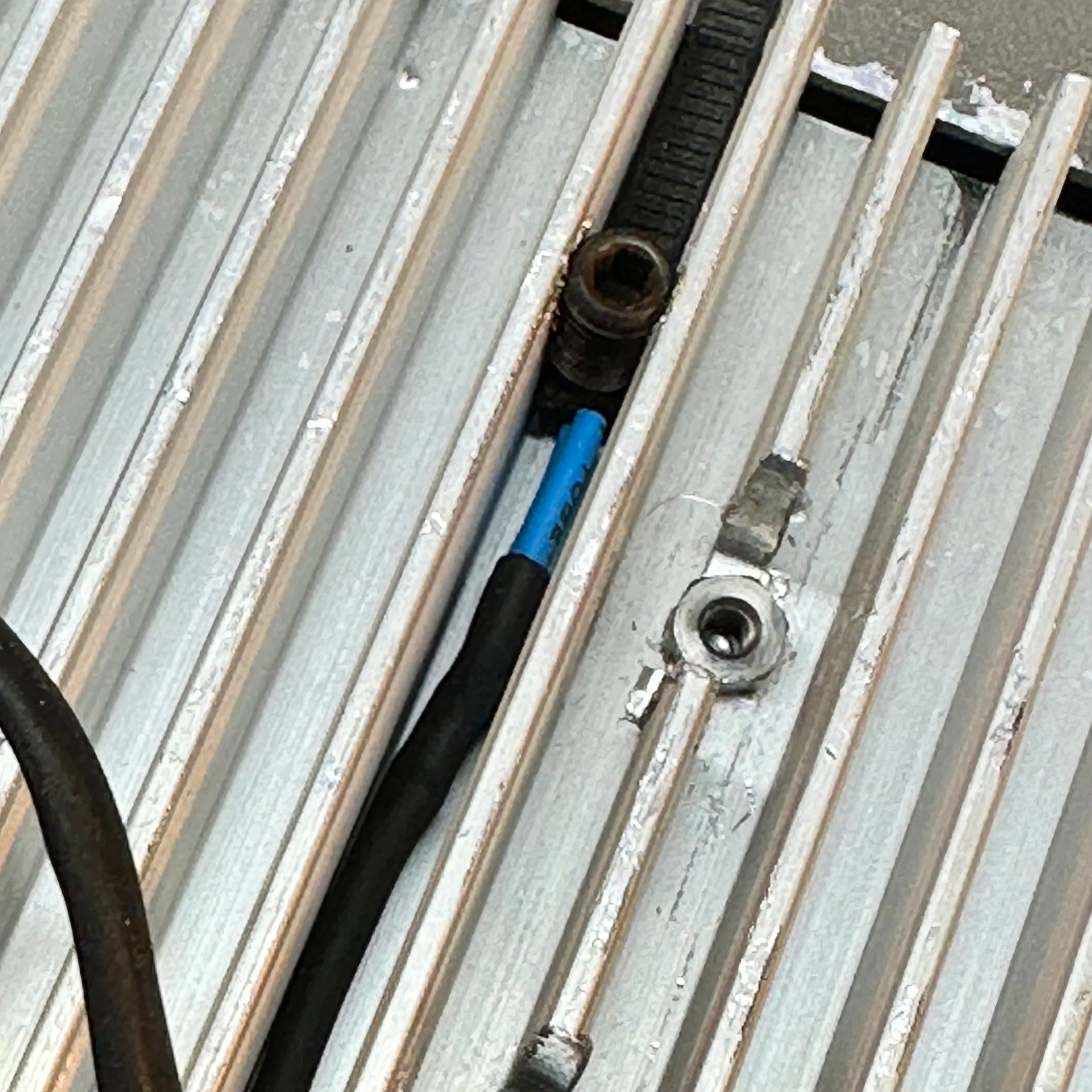
Well knowing this, as per the chart above when the temp rises to about 107 degrees then the resistance drops in the thermistor to about 4980 ohms and this now allows about .7 VDC to develop across the base of the transistor, forward biasing it. Notice how I made the contact with the hear sink. I soldered on a pair of wires and put heat shrink tubing on them to insulate the connections then I ran a 1/4-28 tap down into the space between two fins cutting something resembling threads into the fins. Then I took a piece of a zip tie and put it on the thermistor and ran a setscrew down against the ziptie/thermistor stack to hold the thermistor against the heat sink it works really well too. The ziptie is only there to do two things, to prevent me from cracking the outer shell of the thermistor and to insulate the thermistor from the setscrew so the setscrew wont bleed off heat, I am not certain it helps, but it sounded good in my head at the time. LOL. I located it near the transistors so it will pick up the heat faster. I also changed the mica thermal spacers out for aluminum ceramic instead as those are supposed to conduct heat significantly better between the power transistors and the heatsink.

The fan control circuit can be seen on the perf board next to it in this photo.
Then once things heat up the fan spools up and blows on the heat sink, in turn cooling it down to the point where the temperature on the thermistor drops enough to raise the resistance back up and shut off the transistor again. This worked like a charm at the last activation I used the sBitx v2 on. The fan doesn’t even come on to drain the battery until the heat sink warms up enough to need it, so if your simply listening around or hunting activators and doing search and pounce, then the fan will not cycle on very often at all… if ever. I do understand that there is some current flowing through the resistor network all the time though as well, but it is low and I am not really worried about 3mAs of current anyway. I have really large batteries in the grand scheme of things and if I am going to hike with a radio it will be the Penntek TR-35 anyway…

The next “upgrade” I did to mine was to add a heat sink and fan module to my Raspberry Pi 4 SBC (single board computer) that is the heart of the sBitx radio. The original configuration has the SBC mounted right on the RF board with very little space between the two for airflow and no room at all for a fan of any kind as you can see above in the photo with the side radio cover removed. I did some experiments with positioning fans above the heat vent opening above the Pi and could feel that the air I was pulling out was quite warm. This led me to the assumption that the SBC would run smoother (and probably last longer) if it had a proper heat sink installed on it. You see as my unit would run, with time, it would start to lag a little from information input, like adjusting the VFO would result in the numbers jumping on the display instead of a smooth change as the knob is turned. I noticed when the fan was pulling air across it that this would be reduced significantly if not eliminated. So the mission became “how do I get a fan on this thing to cool it properly”
So I start looking at adding an external fan but ultimately that didn’t look really feasible as I wanted to pull the heat off of the Pi properly and not with just slight air movement. A case fan would only help a little and I am pretty sure at this point that the SBC needs a little more help than that. Enter a riser kit from amazon and a heat sink assembly with fans from one of those Raspberry Pi bundles that comes with the pi, a small case and a heat sink with fans. I measure every thing and come up with a height to elevate the SBC and check the cabinet and sure enough, there is plenty of room to add it. So I get it all together and when you get the riser kit from amazon, you get the little screw-in standoffs as well as the header socket extender to extend the pins up to the Pi once installed. If you will look closely in the photo below, you can see one of the fans and the heat sink fins for the SBC heat sink that I added to the Raspberry Pi SBC to help cool it.


In the above photo you can see the pin extender i also had to add so the Pi would plug in once elevated for the heat sink module. This worked wonderfully for fitment and I was stoked to have the heat sink on the SBC finally, but I still had to connect the fans to power to get them to run. Instead of putting them on a heat sensor, like the power amp fan, I chose to wire these straight to the main power switch on the sBitx so that when you turn it on, they spool up and run the whole time. My reasoning is that the computer will be working the whole time as the radio is in constant “refresh” mode so to speak as the sBitx software package has to keep everything up to date in real time on the display, then there is the background applications that are also running like the telnet server and dx cluster stuff and the other applications should they be active. Logically the SBC will be running nonstop, so lets just run the fans all the time…
This is where I run into a problem…
Did you notice where I drew power to run the fans? That seems completely reasonable for someone who just successfully wired up a fan on a temperature sensing circuit for the power amplifier. Well, it turns out that the fans for a Raspberry Pi are not 13.8VDC fans but rather 5VDC fans as they are designed to be plugged into the SBC IO header bus and not driven from a 13.8 VDC source. Let me tell you something, when you run a 5 volt fan on nearly 14 volts it sounds like a jet engine preparing for take off! On top of that, I had a pair of them!
I had brought the radio to the house and connected it to power to play with it and hunt some POTA activators and the whole time I am thinking to myself… “Man, these tiny little 25mm fans sure are loud…” but after about 10 minutes (yes, they lasted that long and in fact lasted much longer) I started to smell hot plastic… I shut down the radio and took it apart to find the fans incredibly hot and seriously, “soft” to the touch.
Back to the workshop and I figured out what I had done. So I start working on a way to lower the voltage that would not cause RF hash inside the radio cabinet. Those little buck converters from amazon are notorious for causing RF hash so that was out. This simplest thing to do was to put a big resistor in series with the fans. I had put them on a 5 VDC supply in the shop and measured the current draw so it was a simple matter to do a little ohms law and come up with about 50 ohms of resistance to mitigate the excess voltage from the supply. Also these fans pull very little current and I am running them at 4 VDC instead of the full 5 volts as they are rated to run from 3.3 to 5 VDC. This way they will be a little quieter too or at least that is my thinking and it gives me a little leeway should the voltage go down lower or even a little higher.

Inside this heatshrink is (4) 200 ohm 5 watt resistors soldered in parallel so make a 50 ohm 20 watt resistor.
Well the brute force approach worked and the (4) 200 ohm, 5 watt resistors in parallel dropped the voltage down to a very workable level. The resistors dissipate about 1/2 of a watt of heat total so I put them out of the way from everything else and it works, it just works. Maybe later I will add some sort of active voltage regulator and do it so that I don’t have to just burn off the excess power nonstop to keep the fans at the right speed. Maybe something like a 555 timer biasing a mosfet for pulse width modulation to keep the power draw down and keep fan speed at a constant level. I don’t know, I will look at that later, for now, the brute force resistor idea is working just fine.
Once I got the fans turned back on, I found “I had a rod knocking” in one of the fans… figures that if you run them at almost 3 times the rated voltage that something like a bearing fails in the fan… well I just ordered another set from amazon and swapped them a couple of days later and now we are all set. So it would seem at least as when I went to reassemble the radio I found that my USB and Ethernet ports no longer lined up with the openings in the side plate for the radio.

Turns out that if you have a fully equipped machine shop, this isn’t a real problem though. It could have been solved with a good file and probably a half hour of work, but who wants to do that if you have a CNC milling machine at your disposal? So I put it in the milling machine and manually open up the exiting holes to allow use of the ports and by default I also created air vents for the Pi to get fresh air to it much easier now. This also seems to work really well for the time being. Better air flow, adding a heat sink and FANS!!! The Pi runs cool now.

I also did a couple capacitor mods that I found on YouTube as well. A fellow on the interwebs had done these same capacitor mods and they made sense to me so I went ahead and added them as well. The following video describing these mods and why.

To summarize his video, he added decoupling capacitors to the three jacks on the side of the radio to drain off stray RF. He also adds one across the incoming supply lines to kill transients and possible RF on the power. Please note that in the photo below I have the plus side marked on the capacitor, this is incorrect as the board is marked erroneously and I translated that error to my cap as you can see in the photo. Check the supply on your radio with a meter before installing caps that can not be reverse biased. We all know how that would end…


One last thing I also did was to add some heatsinks (also per the video above) to the power devices inside the radio to help them survive use during digital modes. They worked just fine when I ran them with CW but when operating digital, the duty cycle is a lot higher so I didn’t want to risk thermal failure because of something as simple as adding a heat sink. This also comes from the above video and just made sense to me too, so I added them. The radio operates great and I really like using it for FT8 when calling CQ (more on this later) as well as for CW. I have some other mods planned for the future so another blog post describing these mods will be in order at some point. Till then, thanks for your time and attention and I hope this helps someone out there with their radio.
WK4DS
72