

As well as the small stash of finished projects that grace my living space, I also have two small boxes containing various boards. Some of them are boards from part-finished projects that didn’t work. For whatever reason, I ran out of steam and, instead of troubleshooting them, put them carefully into a small box along with their cellmates, and conveniently put them out of my mind. A few of the boards actually worked, but I decided not to case them up. One of these is the two-transistor transmitter I built a few years ago, that was basically the TX side of the Pixie 2 design. I like to pull boards like this out of the box from time to time and power them up. Then they go back in the box, waiting for the next time I feel partial to some extra-curricular fun.

Extricated unceremoniously from it’s cardboard box on the shelf, this little transmitter (pictured above) was putting out about 200mW when connected to a 12V supply. I got a real kick from hearing the signals from this simple circuit on the KPH online SDR at the Point Reyes coastal station, 41 miles away as the crow flies. This design has the oscillator running continuously. In the Pixie, from which it was taken, the oscillator is needed on receive as well. As the circuit consists of just an oscillator and a PA stage, there is a small amount of oscillator leakage into the PA even when the PA stage is not being keyed. Imagine my surprise on discovering that I could hear this backwave on the KPH online SDR! Putting the transmitter on my OHR QRP Wattmeter revealed that although accurate measurement was not possible at such low power levels, it looked as if something of the order of a milliwatt of RF energy was making it’s way to the antenna when the transmitter was not being keyed. Now, the fact that 1mW could be heard 41 miles away, though impressive, is by no means unprecedented. Nevertheless, it fired up my imagination, and made me want to build another little transmitter.
The train of logic that I followed in order to finally settle on building GM3OXX’s little OXO Transmitter was, as it turns out, not very logical and quite convoluted. I will not attempt to explain it here, as it will only serve to confuse! However, I did want a design in which the oscillator wasn’t running on key-up, so that I could monitor the signal in the receiver to serve as sidetone.
The OXO transmitter was first featured in the Autumn 1981 issue of SPRAT, the journal of the G-QRP club. The original circuit didn’t include an LPF; the builder was expected to provide their own. Here is the original circuit, with the addition of an LPF –

The BCY39 PNP transistor keys the +12V supply to the 2N3866 PA. It is not necessary to key the oscillator, as the oscillator won’t run unless the PA transistor is switched on. In the LPF, the 1.38µH inductors can be made with 21 turns on a T37-6 toroid, and the 1.7µH with 24 turns on a T37-6 toroid. Values were taken from the assembly instructions for the QRP Labs low pass filter kits. Numbers of turns for different toroids can be figured out from the very useful calculators on the Kits and Parts website.
I mocked it up on a breadboard and it worked well. I noticed that the VXO, although not oscillating on key-up, was emitting some very low level spurii. In retrospect, this could well have been due to stray capacitances in the breadboard, and the fact that the circuit wasn’t built over a ground plane. Nevertheless, I decided to have the keying transistor key both the oscillator and PA. This is what I came up with, drawn on the back of an envelope –

George GM3OXX added a 0.1µF cap across the key contacts to help with shaping. It wasn’t on the original schematic as published in SPRAT, but I added it here. The RFC in the collector of the PA transistor can be a molded choke. I wound 17 turns on an FT37-43 toroid to serve the same purpose. I also added a spotting switch, with the 1N5817 diode to prevent the PA from being switched on when only the oscillator signal is wanted, for “netting” the transmitter frequency on a receiver. Unfortunately, the spotting switch didn’t work out quite as planned. More on that later.
I had an old LMB Heeger 143 enclosure lying around from my build of N6KR’s SST. I had drilled the front panel holes in the wrong places, so ditched it and used a fresh enclosure. I had considered this enclosure to be unusable for another project, until realizing that I could simply place a piece of PCB material over the front panel to cover up the unused holes, and keep it attached with the nuts and screws that were holding the controls in place. It worked well and looks pretty good. The slide switch is for transmit/receive switching, the red button is for spotting, and the big knob is the VXO tuning –

The board was scrubbed with a steel wool soapy pot scrubber and given a couple of thin coats of clear spray-on lacquer. A fresh board holds so much potential, and never looks as good as before construction begins. It’s almost a shame to glue any pads onto it!

The slide switch was part of an order that I received from Dan’s Small Parts & Kits back in 2011. The polyvaricon was from the VRX-1 direct conversion receiver, designed by NT7S and kitted by 4SQRP. It was one of my first ever Manhattan construction attempts and, although the receiver worked well, I wasn’t happy with my layout and the way my build looked.
All the back panel connectors (key jack, DC power connectors, and BNC’s) were from Tayda. I’m not blown away by the quality of the connectors from Tayda but considering the very reasonable prices, I am making an exception.

I built the VXO first, and tested the frequency coverage. Most any small signal NPN transistor will work in this position. I used a 2N3904. A 2N3866 was used in the original circuit for the PA. I didn’t have one of those, but I did have some 2N3866 equivalents in the form of the Motorola 4-247 CG9949. A while back, the G-QRP club were giving away small quantities of these transistors for free to their members. I took advantage of the offer, knowing that I could use a 2N3866 equivalent or three. This is the exact same transistor that Kanga UK are using for their kit version of the OXO transmitter.
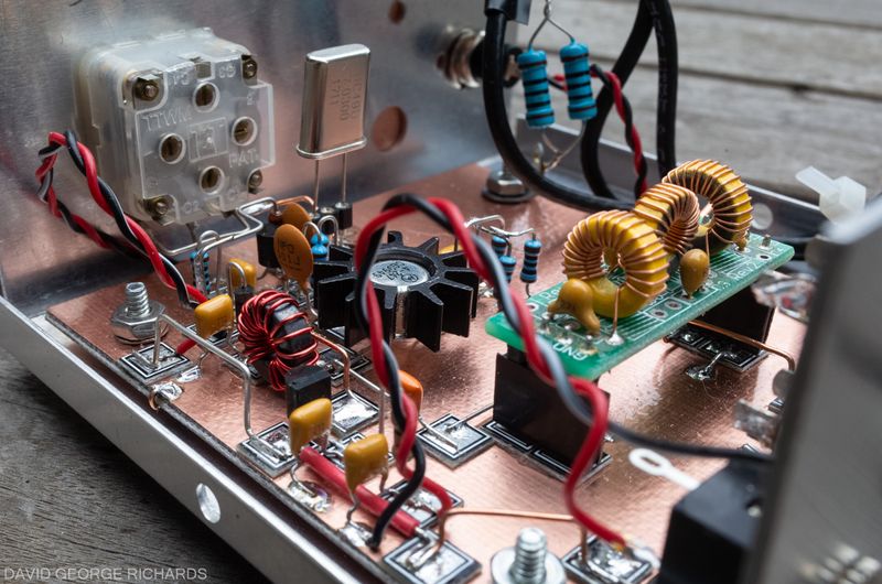
At this point, after having built the VXO and PA circuits, the OXO will function as a transmitter, by keying the +12V line. If you only ever intend to use a manual key with this transmitter, it is not necessary to build the keying switch, and you’ve got yourself a nice and simple two-transistor transmitter. However, I like using a paddle, and the keying circuit is very simple. Here’s the board with the basic transmitter built. You can see the crystal, in a holder made from an SIP strip, along with the VXO transistor, right next to the polyvaricon. The PA transistor is the one with the big honking heatsink on it, just behind the toroid. The keying transistor, a 2N3906, is to the right of the toroid –

For transmit/receive switching, a primitive solution was found, in the form of a DPDT slide switch that came from Dan’s Small Parts and Kits years ago, and has been sitting in one of my parts drawers, just waiting for an opportunity to be used. It was wired up like this (another diagram drawn on the back of an envelope!) –
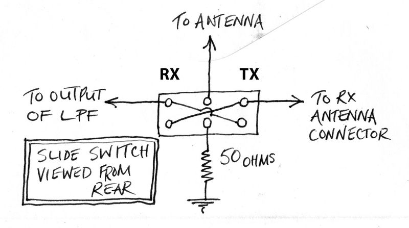
On receive, the antenna is connected to the antenna input of the receiver. The output of the transmitter is connected to a 50 ohm dummy load. In case the transmitter is accidentally keyed while in receive mode, it’s output will be protected by the 50 ohm load. On transmit, the output of the transmitter is routed to the antenna, while the receiver antenna input is connected to the 50 ohm load. The receiver is being used for sidetone, so the idea behind this is to do whatever can be done to prevent receiver overloading while in transmit mode.
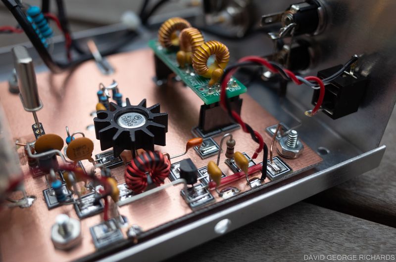
The OXO transmitter, all wired up and ready to go. I used an LPF from QRP-Labs. Band changing can be accomplished by plugging in a different crystal and plugging in a different LPF –

Regarding the PA emitter resistor that is marked as 39Ω. You can fine tune the value of that resistor, depending on the output power you want. Be careful not to go too low, or the transistor could overheat and be destroyed. In the Kanga UK kit version that uses the exact same PA transistor, the emitter resistor is 2 x 33Ω resistors in parallel, for a total effective resistance of 16.5Ω. In the build instructions, Paul reports that with a 13.8V power supply, he gets 1.5W out on 80M and 1W on 40M. I was cautious, and began with 2 x 100Ω resistors (=50Ω). I added resistors in parallel, until I got to 4 x 100Ω (=25Ω). My OHR QRP Wattmeter indicated an RF power out of 400mW. My NM0S QRPometer indicated a power out of 580mW. I wasn’t sure which one was more accurate, so split the difference and called it 500mW. I could get more power by adding another couple of 100Ω resistors, but I rather like the idea of having a 500mW transmitter. By comparison, 1W seems so pedestrian! With an emitter resistance of 25Ω, the voltage across it was 3.2V. According to ohm’s law, the current through it was 128mA, for a dissipated power of 0.41W. The resistors are 1/4W parts, so their total power dissipation capability is 1W. Sounds well within the margin of their capability.
In the following picture, you can see the two 100 ohm 1 watt resistors that form the 50 ohm dummy load in the background –
The heatsink on the PA transistor is probably overkill for a power output of just 500mW, but it gives a good safety margin. I held the key down for 2 minutes (into a dummy load, of course), and it only became mildly warm to the touch. I think it would safely survive even if my cat fell asleep on the key 🙂

The two 12V DC connectors on the back panel are wired in parallel, to allow one 12V lead to power both the transmitter and a companion receiver. It is not shown in the schematic, and cannot be easily seen in any of these pictures, but a 1N5817 diode is wired between the +ve side of the 12V DC connectors and the board, for reverse polarity protection.

I paired it up with my Rugster direct conversion receiver and QSO’ed with K6KWV in Diamond Bar, CA on 40M – a distance of 363 miles as the crow flies. Not mega-DX, but it was a very enjoyable contact. He said that I was the first contact he’d had with a station using a homebrew rig, and I was also running the lowest power of any station he’d QSO’ed with. That was nice to hear! He has only been a ham for 4 months, and has a good fist. His code is pleasant to listen to, and easy copy.
When using the Rugster, as well as throwing the TX-RX switch when going from receive to transmit, I also have to turn the RF gain control down to zero to prevent the receiver from overloading. If on headphones, I also have to turn the AF gain down somewhat. Although it is an easy process to get used to, I find my Belka-DX even easier. Due to the AGC in the Belka, I don’t have to change a thing when going from receive to transmit, and vice-versa, other than flipping the TX-RX slide switch on the OXO transmitter.
The CW note sounds good on 40, and chirp-free. There is a little chirp with my 14060 crystal, and a lot with the 21060 and 28060 crystals. I credit this to the PA loading down the oscillator, and figure that a buffer stage between the oscillator and buffer would cure it. Thanks to John KC9ON, at 3rd Planet Solar, I have a pack of 40M crystals that are in HC49/S cases – the short cases. My 14060, 21060, and 28060 crystals are all in the tall HC49/U cases. Perhaps the higher band crystals are not fundamentals?
On a related note, comparing my HC49/U 7030 crystal with the HC49/S one, the tall crystal pulls over a wider frequency range. I didn’t think to measure the capacitance of the polyvaricon before installing it, but I think it is 270pF per gang. Putting both gangs in parallel made little difference to the pulling range. With the tall HC49/U 7030 crystal, the range was 7028.77 – 7032.83KHz, representing a swing of 3.61KHz. By contrast, the short HC49/S crystal pulled from 7029.57 to 7031.1KHz – a swing of just 1.53KHz. Pulling range became increasingly greater with the higher frequency crystals. The 28060KHz crystal pulled over a range of 13.42Khz, but chirped so much it was comic.
Oh, about that spotting button. I thought I’d be able to use it to net the transmitter precisely on a received station’s frequency. Unfortunately, the frequency of the VXO is significantly lower in spot mode than on full key-down. On 40M with a short crystal, the difference is 250Hz. I assume this issue wouldn’t exist with a buffer stage between the VXO and the PA.
For the time being, I am going to give this project a rest and concentrate on other things. We all need a break sometimes. However, if and when I revisit this little transmitter, I’d like to rewire it so that just the PA is keyed, as was intended with the original circuit. Given that the oscillator doesn’t run unless the PA transistor is switched on, I see no reason not to do this. It is an easy change to make. I’d also like to acquire and try different crystals for the higher bands, in the hope that will eliminate the chirpiness.
Another future possibility would be to add an SMA connector on the back panel for an Si5351 VFO. At that point though, the project is becoming more complex, perhaps negating the point of such a simple transmitter to begin with.


Dave,
Another excellent post.
We had a nice family gathering last night to celebrate my mom’s 102nd birthday which included a berry pie, ice cream and a German chocolate cake! It may be her love of sweets that has contributed to her long life even though she has always been on the slim side.
I can give you a call either later this afternoon or evening or tomorrow so let me know what works for you.
I would like to ask you about your favorite mixers (not cocktail mixers) for use in direct conversion receivers.
Plans for moving my friend into a memory care center continue to evolve but as of today it looks like we can meet later Tuesday afternoon or evening or Wednesday morning before I catch the train from Jack London Square at 9:09 am. Or both. I really enjoy outer get togethers and I always learn so much.
My daughter arrived from Berkeley yesterday for my mom’s party and we will be driving back to her place on Sunday afternoon.
Let me know what works for you!
DK
Brought to you by your friendly fermions and bosons!
The pie, ice cream, and cake sound wonderful DK. My weaknesses!
Tuesday afternoon/evening might be best for a meetup. Wednesday morning may not leave enough time, in case we find our conversation becoming long and detailed!
I have definite opinions on mixers for DC receivers. My favorite comes at the expense of extra circuit complexity but, in my humble opinion, it is worth it. Will share when we talk.
Anytime this afternoon or evening would be best for a call, I may be attending a local tulip exhibition on Saturday. Talk soon.
73 for now,
Dave
Dave,
Let’s talk this afternoon. I will text you first. Do you remember Tiny Tim’s “Tiptoe through the tulips with me”?
DK
Sent from my iPhone
Sure do. I have a copy of it, from a compilation called “Legends of Ukelele”!
So happy to see another AA7EE rig. You know Dave, several of us (Pete N6QW, Dean KK4DAS, me, others) have boxes marked “Boards that Could Become Rigs.” Glad to see you have one too. Please make sure it is marked properly.
And I gota a chuckle about your key up backwave being detectable. Back in 1993 in the Dominican Republic I was running the VXO 6 Watter from QRP classics. The oscillator stayed on, while the driver and PA were keyed. Stations reported hearing my key-up “back wave.” FB!
73 Bill N2CQR
“Boards that could become rigs” is definitely a thing Bill! I am glad that you mentioned it, because it gives me permission to build with unfettered abandon. If a rig doesn’t get finished, or has performance issues, it can still qualify for residence in the “Boards that could become rigs” box. I’m not fond of the crestfallen feeling when a fledgling circuit doesn’t make it to completion, but occupancy in that box is not a complete failure; rather, it’s a purgatory of sorts that might one day result in redemption.
There is always hope!
73 for now,
Dave
AA7EE
PS – great backwave story!
Dave: Your OXO post stirred fond memories of backwaves. I found a discussion of this:
https://www.soldersmoke.com/soldersmoke117.mp3 Shift forward to about 8:15. It turns out Mike Rainey AA1TJ was also getting reports of backwave. There is also dicussion of the somewhat related problem of “backwash.”
I followed up on all this with a blog post about MikeRainey and his backwave experience:
https://soldersmoke.blogspot.com/2009/09/aa1tjs-nifty-fifties-pixie.html
Mike put the power level of his backwave at 100 uW. That’s 100 MICRO watts. In that QSO, this was the equivalent of 1 million miles per watt.
FB! Long live the backwave! Viva!
73 Bill N2CQR
That’s great Bill and, as I mentioned underneath that blog-post, I’m only surprised that 100µW wasn’t Mike’s main intentional radiated signal on key-down! He has to be the main architect of arcane devices and techniques; a giant in the world of QRPp experimentation.
73 for now,
Dave AA7EE
PS – this is stirring up the QRPp mojo Bill. I have a few specific values of resistors on order to fabricate a step attenuator, so that I can generate an intentional 100µW signal from my positively overpowered 100mW transmitter 🙂 More to follow…….
Would you be so kind and publish photo with vertical projection of full PCB?
I purposely didn’t do that Mac, as it’s a simple circuit. Using the pictures above and the accompanying text, figuring the layout is fairly straightforward. Also, there is absolutely no need to follow my layout. If you have specific questions, I’ll do my best to answer them here.
73 for now,
Dave AA7EE
I just like Your pictures 😉
73
MAc
🙂
Hey Dave ! Great build on the OXO. I would like to build one but I’m wondering if there is an easy replacement for the 2N3866. I’m ordering a few from AliExpress but there’s always the worry of counterfeit parts. I see you used a Motorola device in the final. I wonder if a 2N3053 could work with maybe a few component changes? Thanks ! Jim WB4ILP
Jim – although I haven’t tried it, I think a 2N3053 would work without any other component substitutions necessary. Other transistors I have seen suggested as direct replacements are the 2N2219, BFY51 and 2N4427. Perhaps a BD139 . It doesn’t hurt to try. If you have access to SPRAT magazine, in issue 167 page 8, there is an article with suggested mods for this transmitter. Membership in G-QRP allows you to purchase the entire archive for a mere $5 plus postage. Its a heckuva deal.
Dave AA7EE
OK Dave, I’ve got a few genuine 2N3053 stashed somewhere and maybe a few BD139. Like you say, won’t hurt to try. Yes, I will join the GQRP and order the SPRAT archive. That is a Great resource.
Thanks for the reply and have a great weekend !
Jim